Hello Arduino
arduino Arduino UNO Estimated reading time: 10 minutesWe all use software that can use hardware capabilities and convert our actions into the desired result. But do we understand how everything works on the hardware level? How software code translated into 0 and 1 and how electric current produce magic for us?
I always wondering how things work under the hood. And in my opinion, to say that u understand how something works, u need to be able to create the same thing from scratch. I know - for some object it may require years to get all this knowledge, but we have no other way.
Arduino
One of the best ways to start - is to start from something simple and increase complexity step by step. I decided to start from Arduino. Arduino is an open-source electronics platform based on easy-to-use hardware and software.
This platform allows u to start easy - u just need basic knowledge of c++ and pc with Arduino IDE.
Setup
To setup Arduino and start the experiment we need a few things:
- coding environment
- debugging
- hardware
Coding Environment
As I mention above, Arduino provides its IDE that is quite simple and has only a few buttons.
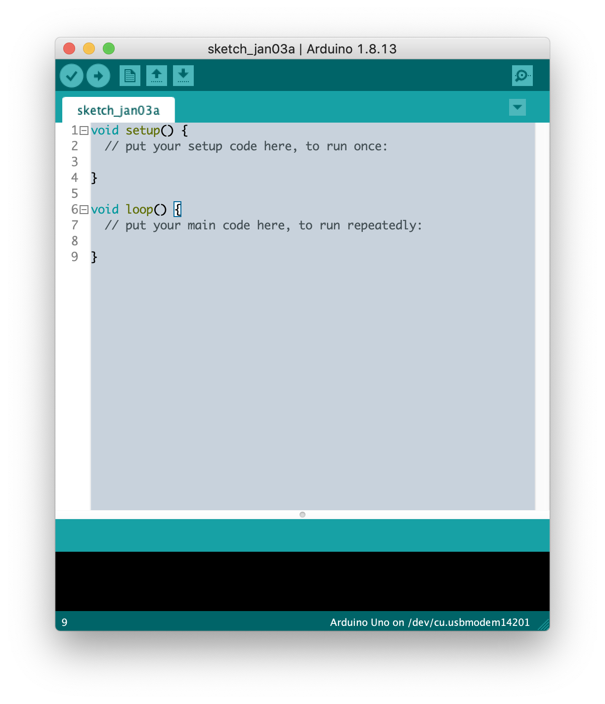
This is great and simple, we may use it for a really fast start. U need just to install it, connect the board via USB and u already should be able to run the program. But at the same moment simplicity bring some limitations:
- no autocomplete
- no build-in documentation
- no possibility to debug
- hard to manage a few source files in projects.
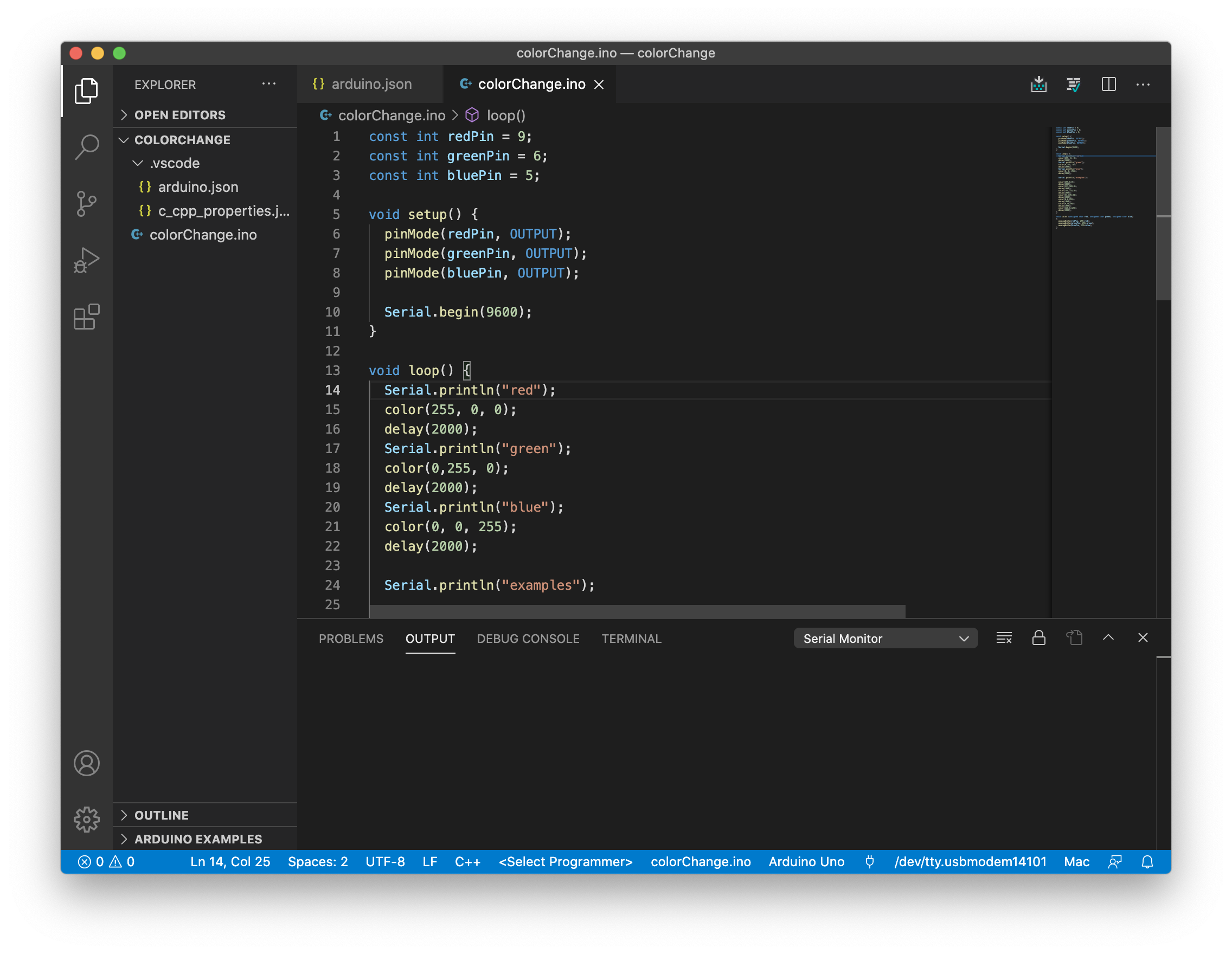
I always prefer to check alternatives before a final decision - here is not an exception. One of the alternative tools - VisualCode vs plugin for C++ and Arduino. This combination brings to us a few advantages:
- autocomplete
- possibility to review documentation (if exist in the source)
- predefined set of commands available from CommandPallete
Such a combination still has some limitations, but a bit less than with Arduino IDE.
Few tips:
- To create project - use command from CommandPallete
Arduino: Initialize
This command will create a project and add additional settings for the project - hidden folder .vscode, where files arduino.json and c_cpp_properties.json are located. In these 2 files, u can setup a configuration for the project.
Check this link about configuration for more
If u like CLI this link also could be useful for u
arduino.json contains all Arduino-specific settings for a project. (alternative for this is CommandPallet actions or bottom panel (described below)).
This is my c_cpp_properties.json:
{
    "configurations": [
        {
            "name": "Mac",
            "includePath": [
                "/Applications/Arduino.app/Contents/Java/tools/**",
                "/Users/kyryl.horbushko/Documents/Arduino/libraries/**",
                "/Applications/Arduino.app/Contents/Java/libraries/**",
                "/Applications/Arduino.app/Contents/Java/hardware/tools/**",
                "/Applications/Arduino.app/Contents/Java/hardware/arduino/avr/**"
            ],
            "forcedInclude": [
                "/Applications/Arduino.app/Contents/Java/hardware/arduino/avr/cores/arduino/Arduino.h"
            ],
            "defines": [
                "USBCON"
            ],
            "macFrameworkPath": [
                "/System/Library/Frameworks",
                "/Library/Frameworks"
            ],
            "intelliSenseMode": "clang-x64",
            "compilerPath": "/usr/bin/clang",
            "cStandard": "c11",
            "cppStandard": "c++17"
        }
    ],
    "version": 4
}
The most interesting part is includePath - contains all the libraries needed.
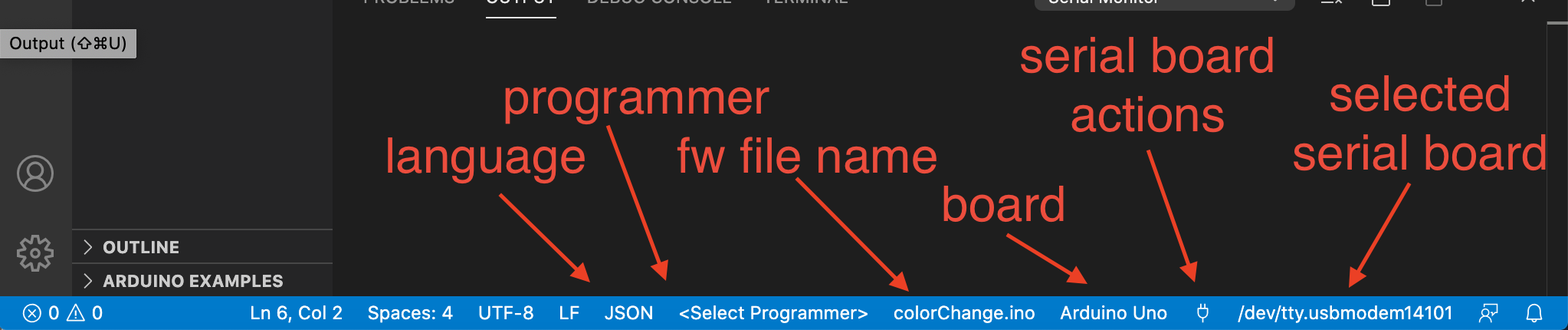
Alternative option - just configure everything from the bottom status panel in Visual code (effect - same as if it configured in arduino.json).
U should select the next items:
- select language - C++,
- select Programmer - the way how your program maybe upload to the device (depend on programmer u have, u may select AVR ISP or left it unselected for USB port)
- set file with fw (if u use a command from CommandPallete than it will be selected automatically. To change - change
sketchvalue in arduino.json) - select board at which u would like to upload fw
- next button with port action - connect/disconnect to the serial port
- and select port which uses for communication
Next few tips:
- To send value over serial port -
Arduino: Send text to serial port - To change baudRate -
Arduino: Change baudrate
To successfully use Serial port make sure u set the correct baudRate in both program and settings.
// u may set this in the sketch setup function to override settings
Serial.begin(9600)- Upload and check code action available from the top right corner of Visual Code
If u like to upload or check code using Arduino IDE, bud write code in some other environment - u may need to select checkmark in setting Use External Editor
- In Arduino IDE, select File -> Preferences -> Check “Use External Editor”
- In VS Code, select the folder you are working on and just code as usual
- If you are ready to upload your code, go back to Arduino IDE and press the upload button
- to support few files within a project (one
.inoand few c++ classes) u need to be sure, that a folder has the same name as the.inofile. Then just position addition.hand.cppfiles in the same folder.
Debuging
Unfortunately debug Arduino is not as easy as u might think. Firstly it’s because of simple IDE - the toolset is minimal and debugging is not included. But we all know a lot of different techniques for debugging - from visual inspection to memory dump analysis.
As for me (at least for now, and at the moment of writing this, I’m not very experience in Arduino), one of the best options is to combine a few practices:
- hardware check
- code analyze
Serialport output (logging)- external tools for debugging (simulators)
Hardware check
This is the very first step that needs to be done. U need to be sure that everything is correctly configured - wires connected properly, components are positioned correctly (check polarity), power system connected correctly.
This small step may prevent half of the problems.
Code analyze
This feature has already been added to IDE and its essential part that allow simply to avoid any typo and lexical errors. Works great within both Arduino IDE and Visual Code.
We also can use the Validate option to compile and to analyze the errors.
As David Thomas and Andrew Hunt mentioned in their book* “The Pragmatic Programmer” - *Read the Damn Error message. It’s cool advice, especially when u have to deal with Arduino ;].
U can also check your code manually to make sure that logic is correct.
Some people can propose to add comments into code. I prefer to avoid them because as soon as u add them into the code, they become obsolete. Better make your code tell the story for others, not the comments. Comments for me - an indicator of workarounds and some unresolved, known bugs.
Serial port output (logging)
This kind of live-session debugging way. U simply add log output and inspect state and variables when something is executed.
Serial.begin(9600)
Serial.println("The variable is ", x)External tools for debugging (simulators)
There are a bunch of them, like Virtual Breadboard. I checked a few and one of the coolest is Circuits.io. This tool allows you to design, prepare instruction, and generate basic code for u.
Hardware
Hardware u can get by visiting the official site of Arduino and by ordering any set of parts. I started from Arduino Starter Kit Uno.
This kit also includes a perfect guide, which as an option available in pdf.
My first app
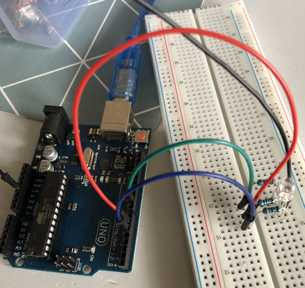
I started with a simple classic app - colored diode. My target - is to assemble a scheme that allows me to change the color of the diode with some command.
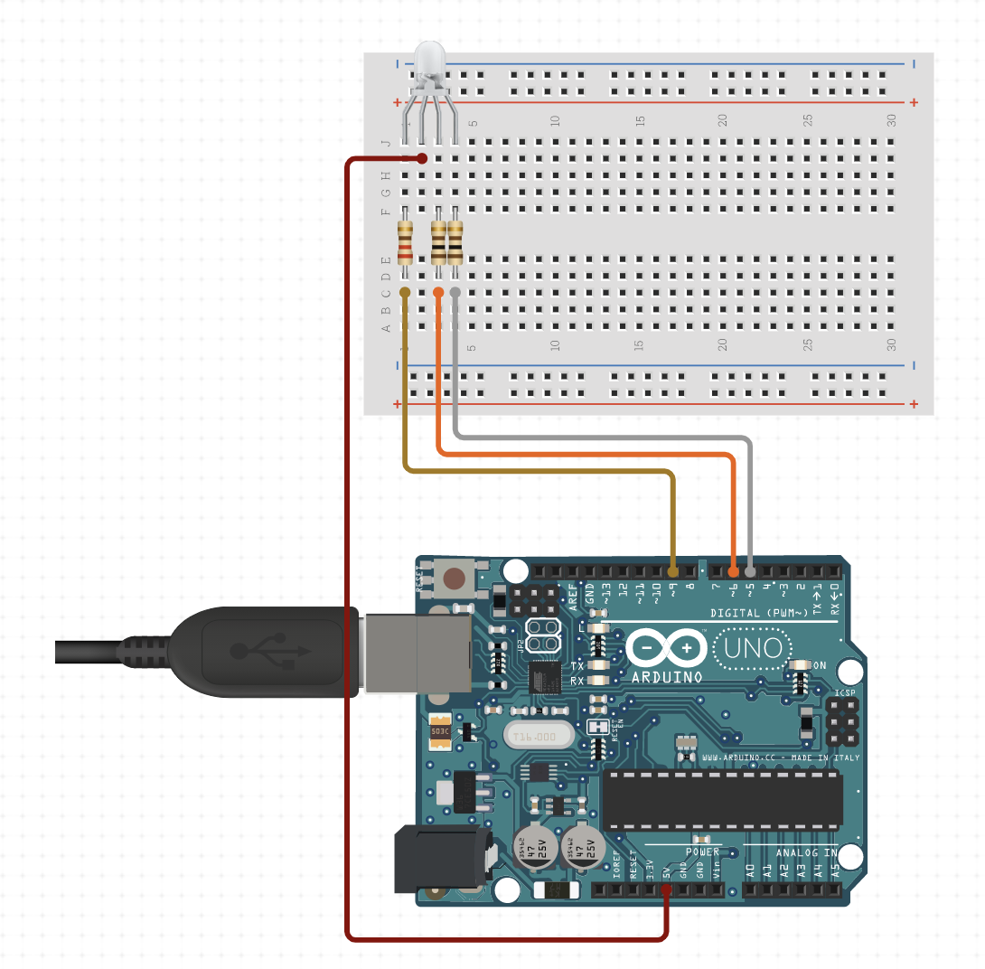
First of all - components. For this board I just needed a few of them:
- 3-color diode (RGB LED Common Anode)
- Arduino UNO vs power cord
- few resistors (diode should be protected)
- some wires to connect
Assembled scheme:
The program idea - just on/off diode with some color. To achieve this we should use a few commands:
pinMode- Configures the specified pin to behave either as an input or an outputdigitalWrite- Write a HIGH or a LOW value to a digital pinanalogWrite- Writes an analog value (PWM wave) to a pin
To use analogWrite we can use any of the pins marked with the
~symbol - 3, 5, 6, 9, 10, 11 for the Uno board
First version of program - simply on different colors in a loop:
const int redPin = 9;
const int greenPin = 6;
const int bluePin = 5;

void setup() {
  pinMode(redPin, OUTPUT);
  pinMode(greenPin, OUTPUT);
  pinMode(bluePin, OUTPUT);

  Serial.begin(9600);
}

void loop() {
  Serial.println("red");
  color(255, 0, 0);
  delay(2000);
  Serial.println("green");
  color(0,255, 0);
  delay(2000);
  Serial.println("blue");
  color(0, 0, 255);
  delay(2000);
}

void color (unsigned char red, unsigned char green, unsigned char blue)
{
  analogWrite(redPin, 255-red);
  analogWrite(greenPin, 255-green);
  analogWrite(bluePin, 255-blue);
}
255-redused because of the connection way of RGB diode.
This is a simple fw that can show 3 colors in a loop. To make a bit complicated sample, we can add some point of control for it - the menu.
colorDiod.ino
#include <Arduino.h>
#include "RGBLed.h"

#define RGBLED_PIN_B	5
#define RGBLED_PIN_G	6
#define RGBLED_PIN_R	9
#define rgbLed_TYPE COMMON_ANODE

RGBLed rgbLed(RGBLED_PIN_R,RGBLED_PIN_G,RGBLED_PIN_B,rgbLed_TYPE);
const int timeout = 10000;
char menuOption = 0;
long time0;

void setup()
{
    Serial.begin(9600);
    while (!Serial);
        Serial.println(F("start"));

    rgbLed.turnOff();
    menuOption = menu();
}

void loop()
{
    if(menuOption == '1') {
    rgbLed.setRGB(160, 3, 255);
    delay(500);

    } else if (menuOption == '2') {
        rgbLed.setRGB(255, 0, 0);
        delay(5000);
    } else if (menuOption == '3') {
        rgbLed.setRGB(0, 255, 0);
        delay(5000);
    } else if (menuOption == '4') {
        rgbLed.setRGB(0, 0, 255);
        delay(5000);
    } else if (menuOption == '5') {
        rgbLed.setRGB(255, 0, 0);
        delay(500);
        rgbLed.setRGB(155, 155, 0);
        delay(500);
        rgbLed.setRGB(0, 255, 0);
        delay(500);
    }

    rgbLed.setRGB(0, 0, 0);
    delay(500);

    if (millis() - time0 > timeout) {
        menuOption = menu();
    }
}

char menu()
{

    Serial.println(F("\nSelect one of the item:"));
    Serial.println(F("(1) RGB Led Common Anode"));
    Serial.println(F("(2) RED"));
    Serial.println(F("(3) GREEN"));
    Serial.println(F("(4) BLUE"));
    Serial.println(F("(5) Red-Yeloow-Green"));
    Serial.println(F("(menu) send anything else or press on board reset button\n"));
    while (!Serial.available());

    while (Serial.available())
    {
        char c = Serial.read();
        if (isAlphaNumeric(c))
        {
            if(c == '1' || c == '2' || c == '3' || c == '4' || c == '5')
    			Serial.println(F("Now Testing RGB Led Common Anode"));
            else
            {
                Serial.println(F("illegal input!"));
                return 0;
            }
            time0 = millis();
            return c;
        }
    }
}
RGBLed.h
#ifndef RGBLED_H
#define RGBLED_H

#define COMMON_ANODE 0
#define COMMON_CATHODE 1

class RGBLed {
	public:
		RGBLed(int redPin, int greenPin, int bluePin, bool type = COMMON_ANODE);
		void setRGB(int R, int G, int B);
		void turnOff();
	private:
		const int rPin,gPin,bPin;
    bool TYPE;
};
#endif
RGBLed.cpp
#include "RGBLed.h"
#include <Arduino.h>

RGBLed::RGBLed(int redPin, int greenPin, int bluePin, bool type): rPin(redPin), gPin(greenPin), bPin(bluePin) {
  TYPE = type;
	pinMode(rPin, OUTPUT);
	pinMode(gPin, OUTPUT);
	pinMode(bPin, OUTPUT);
}

void RGBLed::setRGB(int R, int G, int B)
{
  if(TYPE) {
    analogWrite(rPin,R);
    analogWrite(gPin,G);
    analogWrite(bPin,B);
  } else {
    analogWrite(rPin,255-R);
    analogWrite(gPin,255-G);
    analogWrite(bPin,255-B);
  }
}

void RGBLed::turnOff()
{
  if(TYPE) {
  	digitalWrite(rPin,0);
  	digitalWrite(gPin,0);
	  digitalWrite(bPin,0);
  } else {
    digitalWrite(rPin,1);
    digitalWrite(gPin,1);
    digitalWrite(bPin,1);
  }
}
Note: part of code generated by circuito.io
Now, if u upload this app to the board, u will send Command using CommandPallete and serial port and observe some changes on the diode.
Conclusion
I’m very excited about Arduino and its simplicity of it. Big community and open source projects make it possible to learn quickly and to get some additional knowledge.
Resources
- Download link
- Visual studio code
- Getting Started with Arduino UNO
- Language reference
- Use Visual Studio Code for Arduino
- Learn how you can use the Arduino extension on Visual Studio Code to create programs for your Arduino.
- Multiple source files support
- Enable input for the serial monitor for Visual Code
- About Programmer for Arduino
- Using an External Text Editor in Arduino IDE
- Debugging
- How to debug code in Arduino IDE
- Project hub
Share on: