Arduino crash course
arduino Arduino UNO Estimated reading time: 12 minutesDuring the past few weeks, I spend some time playing within Arduino StarterKit creating very simple and basics schemes and refreshing my memory about schematic and different components used in various PCBs.
Created schemes:
- Active buzzer
- Tilt bolt switch
- Ultrasonic sensor
- Temp and humidity sensor
- LCD
- IR remote/receiver
If u interested in environment configuration for working with Arduino, check out my previous post about it.
Active buzzer
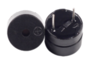
A buzzer - is a simple component that can generate sounds with various frequencies. Buzzers are used a lot in different electronics - from toys to PC. There are 2 types of buzzer - active and passive.
An active buzzer has a built-in oscillating source, so it will make sounds when electrified. But a passive buzzer does not have such a source, so it will not tweet if DC signals are used; instead, you need to use square waves whose frequency is between 2K and 5K to drive it. The active buzzer is often more expensive than the passive one because of multiple built-in oscillating circuits. source
This is a quite simple scheme and u can find a lot of samples for it like this or this
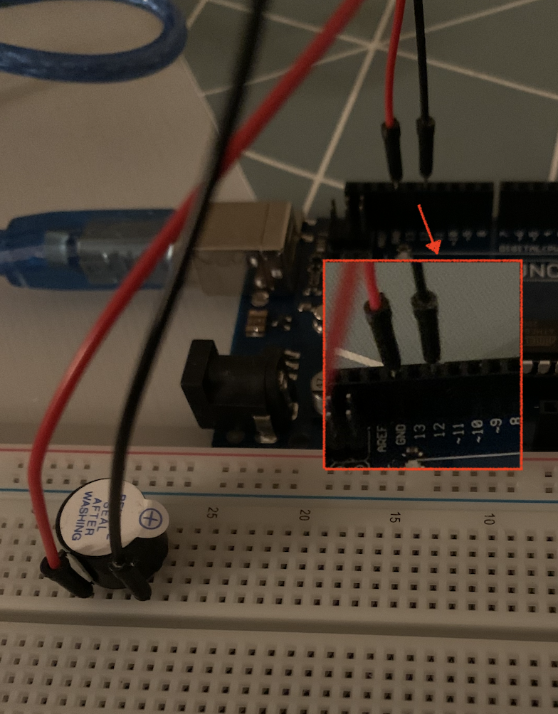
I didn’t reinvent the wheel and just create one of basic scheme:
To make things a bit more interesting, I used this scheme to play a melody from StarWars - The Imperial March (Star Wars, Darth Vader Theme).
To do this, we should do next:
- define notes - this was already done and available on official site
- get notes for selected sound - I used this source
- transform piano notes into a sequence of commands for a buzzer.
To do this, we may use the command tone.
tone(12, melody[thisNote], noteDuration);12 is a number for a pin, to which connected
+from the buzzer.
We also should define noteDuration - this can be figured out from the note’s list obtained from prev steps. We define this as a set of integers, that represent part of a period:
int noteDurations[] = {
...
    9, 12, 12, 2,
    3, 2, 9, 9,
    9, 12, 3, 9,
...
};
u may also use a stopwatch as alternative
melody - is a set of notes according to note’s list:
int melody [] = {
...
    // 5|g-FfF-----D---d-C-c-c-----|
    // 4|--------A----------b----f-|

    NOTE_G5, NOTE_FS5, NOTE_F5, NOTE_FS5,
    NOTE_A4, NOTE_DS5, NOTE_D5, NOTE_CS5,
    NOTE_C5, NOTE_B4, NOTE_C5, NOTE_F4,
...
};
If u want to get silence - use
0
I didn’t play on a piano, so I used this resource to figure out how this works.
So the rest - is just a mechanical work:
void loop()
{
    int melodyCount = sizeof(melody)/sizeof(melody[0]);

    for (int thisNote = 0; thisNote < melodyCount; thisNote++) {
        int noteDuration = 1000 / noteDurations[thisNote];

        tone(12, melody[thisNote], noteDuration);

        int pauseBetweenNotes = noteDuration * 1.30;
        delay(pauseBetweenNotes);
    }

    Serial.print("done");

    noTone(12);
    delay(2000);
}
I know, that timing is not ideal, and I can’t play 2 notes simultaneously using this approach, but this is just a small deviation.
If u like an idea about buzzer song - visit this git for getting more songs
Tilt bolt switch
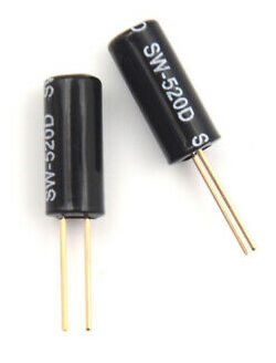
This component is like a simplified accelerometer - it can detect orientation change. Unlike accelerometers, the tilt sensor is smaller, inexpensive, consume less power, but provide less sensitive result.
Inside, this component usually has a conductive ball with free mass. One end of the cavity has conductive elements (poles). When a sensor is oriented in some way, the mass rolls onto poles and shorts them, it acts as a switch.
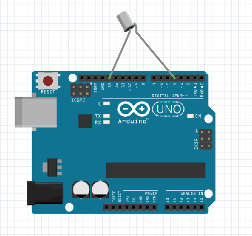
The simplest way to test is to detect switch and, for example, light the diode.
The scheme and photo:
And the code:
const int ledPin = 13;

void setup()
{
    pinMode(ledPin, OUTPUT);
    pinMode(4, INPUT);
    digitalWrite(4, HIGH);
}

void loop()
{
    int digitalVal = digitalRead(4);
    if (HIGH == digitalVal)
    {
        digitalWrite(ledPin, LOW);
    }
    else
    {
        digitalWrite(ledPin, HIGH);
    }
}
As result, we can see diode blink when we change oprientation for the component:
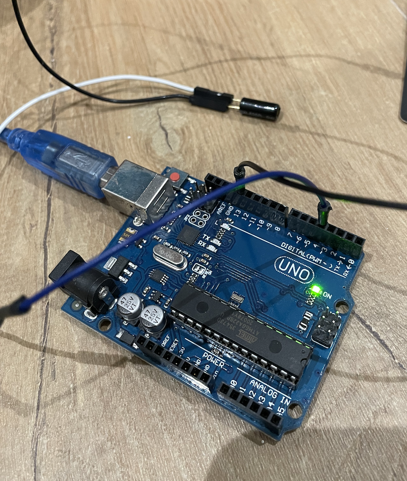
Ultrasonic sensor
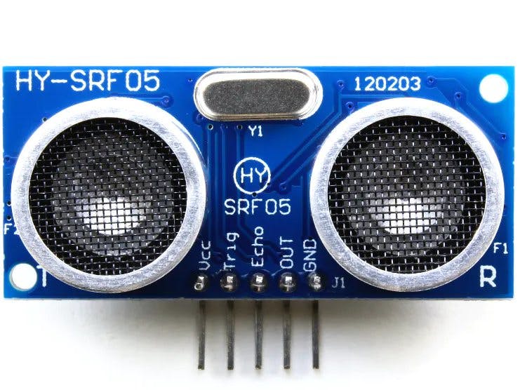
Ultasonicsensor is a great component for simple processes that need measurement of the distance. HC-SR04 - this is a inexpensive component that is easy to configure and use. It’s povide quite good result within small distances (up to 4m) within small angle:
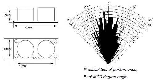
Accuracy according to spec is about 2mm.
The principle of work:
- using IO we should generate at least 10us high-level signal
- module sends 8x 40kHz and detects any puls signals back
- if the signal received, calculate distance based on signal return delay, speed of signal
distance = time x velosity / 2velosity of sound - 340m/s,
division for 2 needed because sound travels forward and back.
The scheme is very simple:
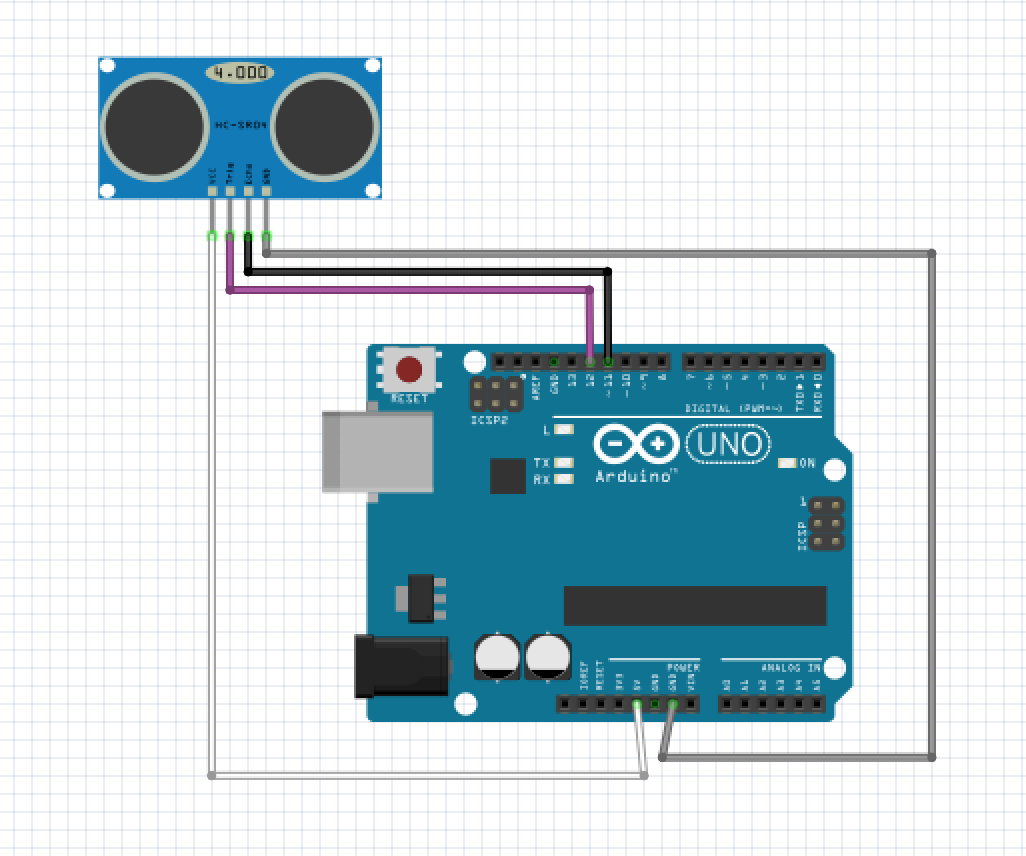
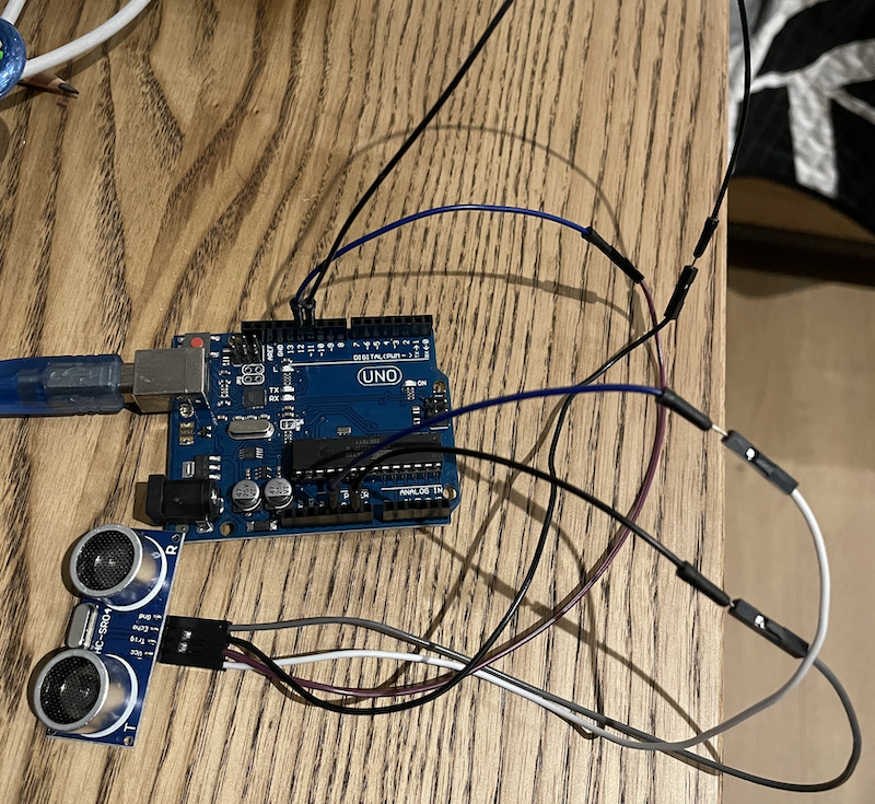
And photo of assembled one:
The code, that reflect this measurement canbe as follow:
#include <Arduino.h>
#define TRIG_PIN 12
#define ECHO_PIN 11
long Duration = 0;
void setup()
{
// Trigger is an output pin
pinMode(TRIG_PIN, OUTPUT);
// Echo is an input pin
pinMode(ECHO_PIN, INPUT);
Serial.begin(9600);
}
void loop()
{
digitalWrite(TRIG_PIN, LOW);
delayMicroseconds(2);
// Trigger pin to HIGH
digitalWrite(TRIG_PIN, HIGH);
// 10us high
delayMicroseconds(10);
// Trigger pin to HIGH
digitalWrite(TRIG_PIN, LOW);
// Waits for the echo pin to get high
Duration = pulseIn(ECHO_PIN, HIGH);
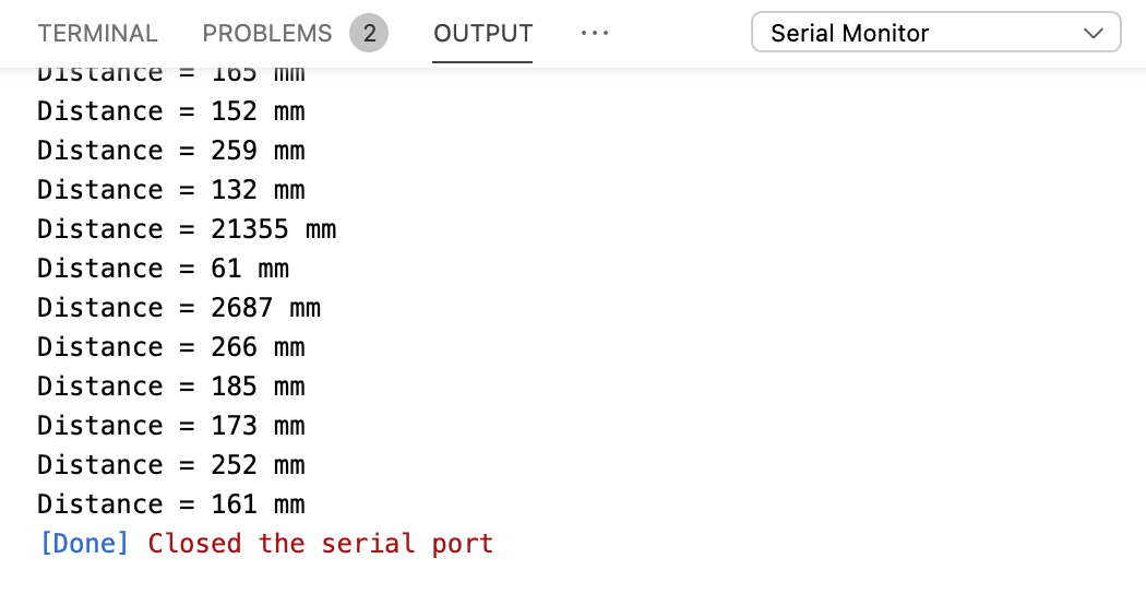
long Distance_mm = Distance(Duration);
Serial.print("Distance = ");
Serial.print(Distance_mm);
Serial.println(" mm");
delay(1000);
}
long Distance(long time)
{
// Calculates the Distance in mm
// ((time)*(Speed of sound))/ toward and backward of object) * 10
long DistanceCalc;
DistanceCalc = ((time / 2.9) / 2);
return DistanceCalc;
}Output:
here is ready-bake library for this sensor
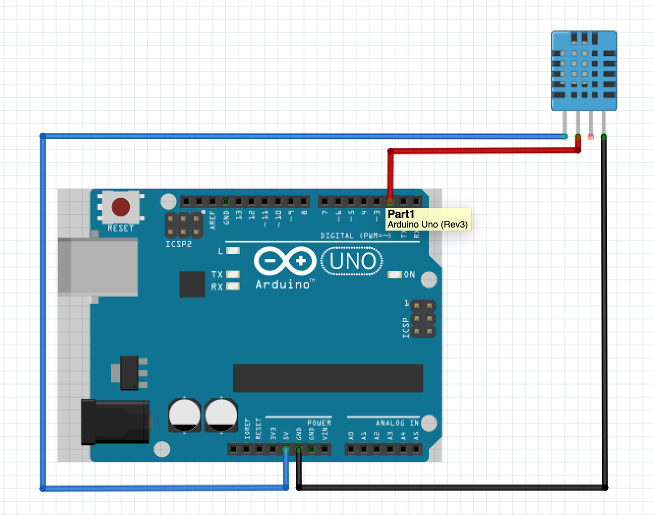
Temp and humidity sensor
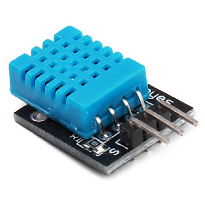
Temp and humidity sensor is another cool sensor that can be used in your project. It’s accurate and small and provides the necessary information required by most applications that need it.
To deal with this sensor I used small library specially created for DHT11 sensor.
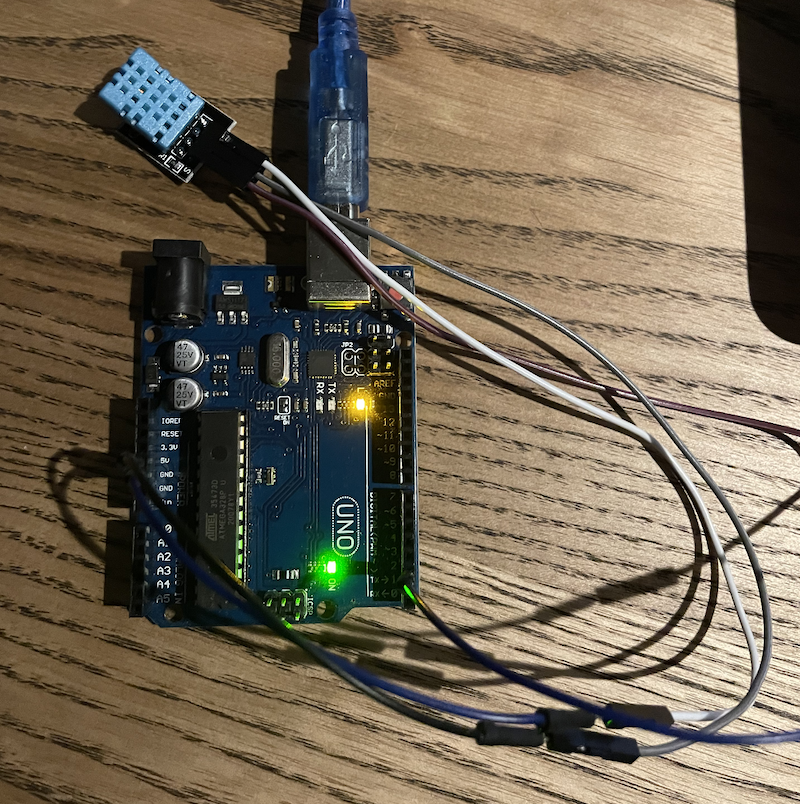
The scheme and a photo of wiring:
And a photo of assembled part:
Using library for DHT11 and one of the source in the net:
#include <Arduino.h>
#include "dht_nonblocking.h"
#define DHT_SENSOR_TYPE DHT_TYPE_11
static const int DHT_SENSOR_PIN = 2;
DHT_nonblocking dht_sensor(DHT_SENSOR_PIN, DHT_SENSOR_TYPE);
void setup()
{
Serial.begin(9600);
}
void loop()
{
float temperature;
float humidity;
if (measureEnvironment(&temperature, &humidity) == true)
{
Serial.print(__TIMESTAMP__);
Serial.print(" T = ");
Serial.print(temperature, 1);
Serial.print(" deg. C, H = ");
Serial.print(humidity, 1);
Serial.println("%");
}
}
static bool measureEnvironment(float *temperature, float *humidity)
{
static unsigned long measurement_timestamp = millis();
if (millis() - measurement_timestamp > 30000ul)
{
if (dht_sensor.measure(temperature, humidity) == true)
{
measurement_timestamp = millis();
return (true);
}
}
return (false);
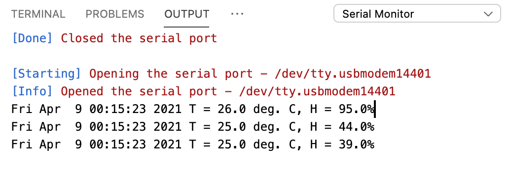
}Output:
LCD
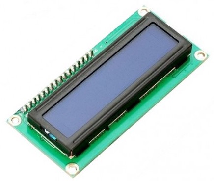
LCD is present in the biggest part of electronic devices and allows users to see information or control work it. I tested LCD with a backlight and 2 rows with 16 characters each.
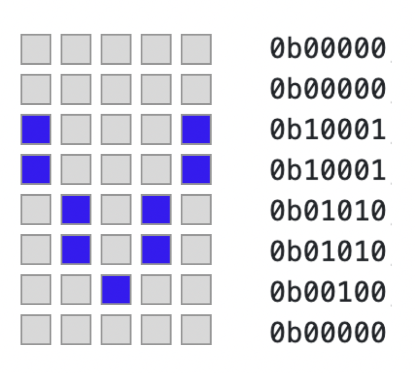
LCD has build in table with symbols - check tech spec for more info. We also can create our own symbol by simply providing mask:
The display has few contacts, the list with contact number and purpose is listed in the table below:
| contact # | mark | purpose |
|---|---|---|
| 1 | Vss | ground |
| 2 | Vdd | 5V |
| 3 | Vo | contrast |
| 4 | Rs | mode |
| 5 | RW | read/write |
| 6 | En | isDataReady |
| 7 | D0 | data line 0 |
| 8 | D1 | data line 1 |
| 9 | D2 | data line 2 |
| 10 | D3 | data line 3 |
| 11 | D4 | data line 4 |
| 12 | D5 | data line 5 |
| 13 | D6 | data line 6 |
| 14 | D7 | data line 7 |
| 15 | A | anode |
| 16 | K | cathode |
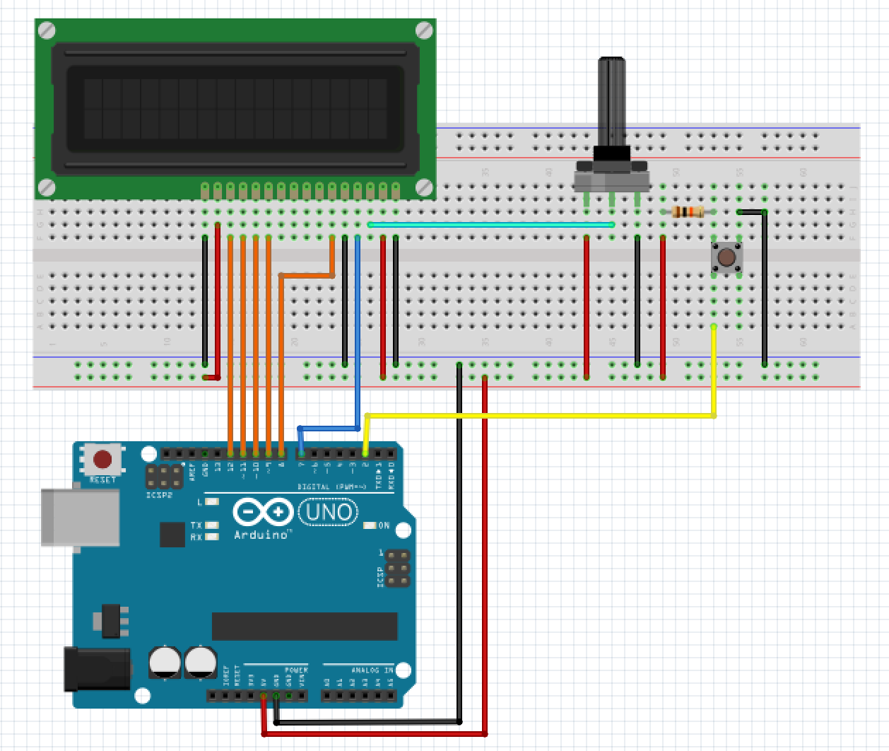
To play within LCD I assembled a scheme that can work in diff modes, demonstrating different possibilities: text, moving line, custom symbols, animation.
The scheme:
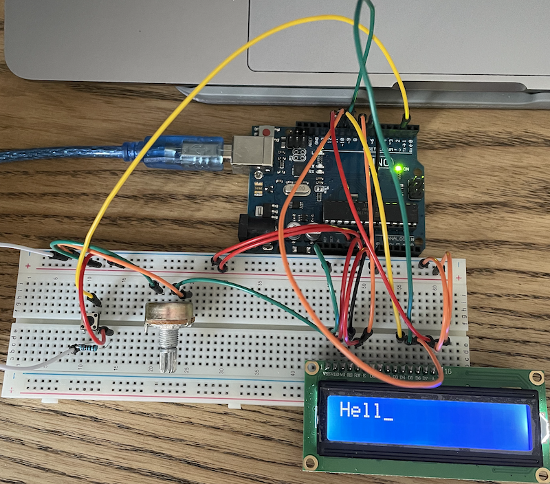
and assembled one (photo):
To make it alive, we can use next code:
// https://github.com/arduino-libraries/LiquidCrystal
#include "LiquidCrystal.h"
#include "Arduino.h"

// register select pin that controls where in the LCD's
// memory we are writing data to
const int rs = 7;
// pin that responsible for data readiness
const int en = 8;

// pins for read/write data; *(d0-d3 not used)
const int d4 = 9;
const int d5 = 10;
const int d6 = 11;
const int d7 = 12;

// custom symbols
byte cyrylicE[8] = {
    0b00011,
    0b01100,
    0b10000,
    0b11110,
    0b10000,
    0b01100,
    0b00011};

byte cyrylicG[8] = {
    0b11111,
    0b10000,
    0b10000,
    0b10000,
    0b10000,
    0b10000,
    0b10000};

byte cyrylicO[8] = {
    0b11111,
    0b10001,
    0b10001,
    0b10001,
    0b10001,
    0b10001,
    0b11111};

byte cyrylicR[8] = {
    0b11111,
    0b10001,
    0b10001,
    0b11111,
    0b10000,
    0b10000,
    0b10000};

byte animationOne[8] = {
    0b00000,
    0b00000,
    0b01010,
    0b01010,
    0b10001,
    0b11011,
    0b00100,
    0b00000};

byte animationDown[8] = {
    0b00000,
    0b00000,
    0b10001,
    0b10001,
    0b01010,
    0b01010,
    0b00100,
    0b00000};

enum Mode
{
    PRINT_MESSAGE,
    PRINT_MESSAGE_AND_PASSED_TIME,
    SHOW_MOVING_LINE,
    SHOW_CUSTOM_SYMBOLS,
    SHOW_CUSTOM_SYMBOLS_AND_ANIMATION,
    MODES_COUNT
};

// configue LCD
LiquidCrystal lcd(rs, en, d4, d5, d6, d7);

// set test mode to check different options
Mode mode = PRINT_MESSAGE;

void setup()
{
    createCustomSymbols();
    createAnimationSymbols();

    configureDisplay();
    configureButton();
}

void loop()
{
    readButtonState();

    switch (mode)
    {
    case PRINT_MESSAGE:
        printMessage("Hello world");
        break;
    case PRINT_MESSAGE_AND_PASSED_TIME:
        printMessage("Hello world");
        displayPassedTime();
        showBlinkingCursor();
        break;
    case SHOW_MOVING_LINE:

        displayMovingLine();
        break;
    case SHOW_CUSTOM_SYMBOLS:
        // configureDisplay();
        printCustomSymbols();
        break;
    case SHOW_CUSTOM_SYMBOLS_AND_ANIMATION:
        printCustomSymbols();
        displayAnimation();
        break;
    default:
        break;
    }
}

void configureDisplay()
{
    // configure lcd to show 16 columns and 2 row
    lcd.begin(16, 2);
}

void printMessage(String message)
{
    lcd.setCursor(0, 0);
    lcd.print(message);
}

void createCustomSymbols()
{
    // create new symbol
    // there is a bug, check next link for more
    // https://forum.arduino.cc/index.php?topic=94914.0

    // letters for displaying my son's name in Cyrylic
    lcd.createChar(0, cyrylicE);
    lcd.createChar(1, cyrylicG);
    lcd.createChar(2, cyrylicO);
    lcd.createChar(3, cyrylicR);
}

void createAnimationSymbols()
{
    lcd.createChar(4, animationDown);
    lcd.createChar(5, animationOne);
}

void printCustomSymbols()
{
    lcd.setCursor(0, 0);

    lcd.print((char)0);
    lcd.print((char)1);
    lcd.print((char)2);
    lcd.print((char)3);
}

void createSymbolsForAnimation()
{
    lcd.createChar(4, animationDown);
    lcd.createChar(5, animationOne);
}

void displayPassedTime()
{
    // print in second line
    lcd.setCursor(0, 1);
    lcd.print(millis() / 1000);
}

void showBlinkingCursor()
{
    // turn off cursor
    lcd.noCursor();
    delay(500);
    // turn on cursor
    lcd.cursor();
    delay(500);
}

void displayMovingLine()
{
    lcd.clear();
    lcd.setCursor(0, 0);
    // moving line
    char message[12] = {'H',
                        'e',
                        'l',
                        'l',
                        'o',
                        ' ',
                        'w',
                        'o',
                        'r',
                        'l',
                        'd',
                        '\0'};
    lcd.setCursor(0, 0);
    int arrSize = sizeof(message) / sizeof(message[0]);
    for (int i = 0; i < arrSize - 1; i++)
    {
        lcd.print(message[i]);
        delay(500);
    }

    lcd.noAutoscroll();
    lcd.clear();
}

void displayAnimation()
{
    // set the cursor to the bottom row
    lcd.setCursor(0, 1);

    // draw the little man, arms down
    lcd.write(4);
    delay(500);
    lcd.setCursor(0, 1);
    // draw him arms up
    lcd.write(5);
    delay(500);
}

// the pin that the pushbutton is attached to
const int buttonPin = 2;
// current state of the button
int buttonState = 0;
// the pin that the LED is attached to
const int ledPin = 13;
// counter for the number of button presses
int buttonPushCounter = 0;

void configureButton()
{
    // initialize the button pin as a input:
    pinMode(buttonPin, INPUT);
    // initialize the LED as an output:
    pinMode(ledPin, OUTPUT);
    // initialize serial communication:
    Serial.begin(9600);
}

void readButtonState()
{
    // read the pushbutton input pin:
    buttonState = digitalRead(buttonPin);
    if (buttonState == HIGH)
    {
        buttonPushCounter++;
        Serial.println("Pressed");
        digitalWrite(ledPin, HIGH);

        if (buttonPushCounter >= MODES_COUNT)
        {
            buttonPushCounter = PRINT_MESSAGE;
        }
        else
        {
            mode = static_cast<Mode>(buttonPushCounter);
        }
        Serial.print("Mode changed - ");
        Serial.println(buttonPushCounter);
    }
    else
    {
        digitalWrite(ledPin, LOW);
    }
}
Libray for work with LCD available on github
As result, u can see next:
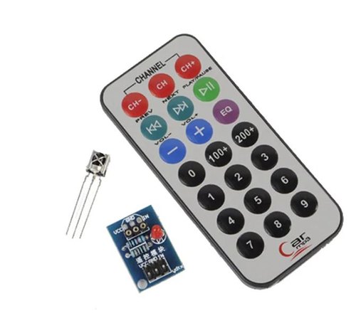
IR remote/receiver
This component well knows by everyone - u use it with your tv or another remote device. It is widely used as one of the easiest ways to get wireless technology.
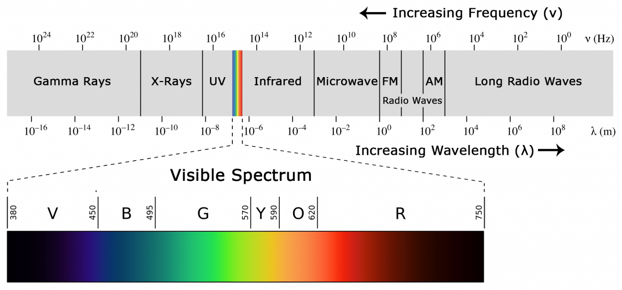
Before testing this component, it’s good to know what is infrared and how this component work.
If we go to wiki, we can find the next explanation: “Infrared (IR), sometimes called infrared light, is electromagnetic radiation (EMR) with wavelengths longer than those of visible light. It is therefore invisible to the human eye.”.
To use infrared light we need at least an IR receiver and remote. Next point - we should somehow determine signal, thus IR light can be emitted not only by our remote, but also by sun and other sources, so there is a lot of noise around. To make this thing possible, IR signal modulation is used. There are a bit ways to do this, so quite a few protocols for communications exist.
To quickly receive IR signal, I used library available on git, but, if u are interested in details, how a signal is decoded - check this link.
To connect the IR-received to arduino, we just need a few wires - ground, power and a connection for reading results from component. To make things a bit more interested, I added few diodes, so we can control them remotely:
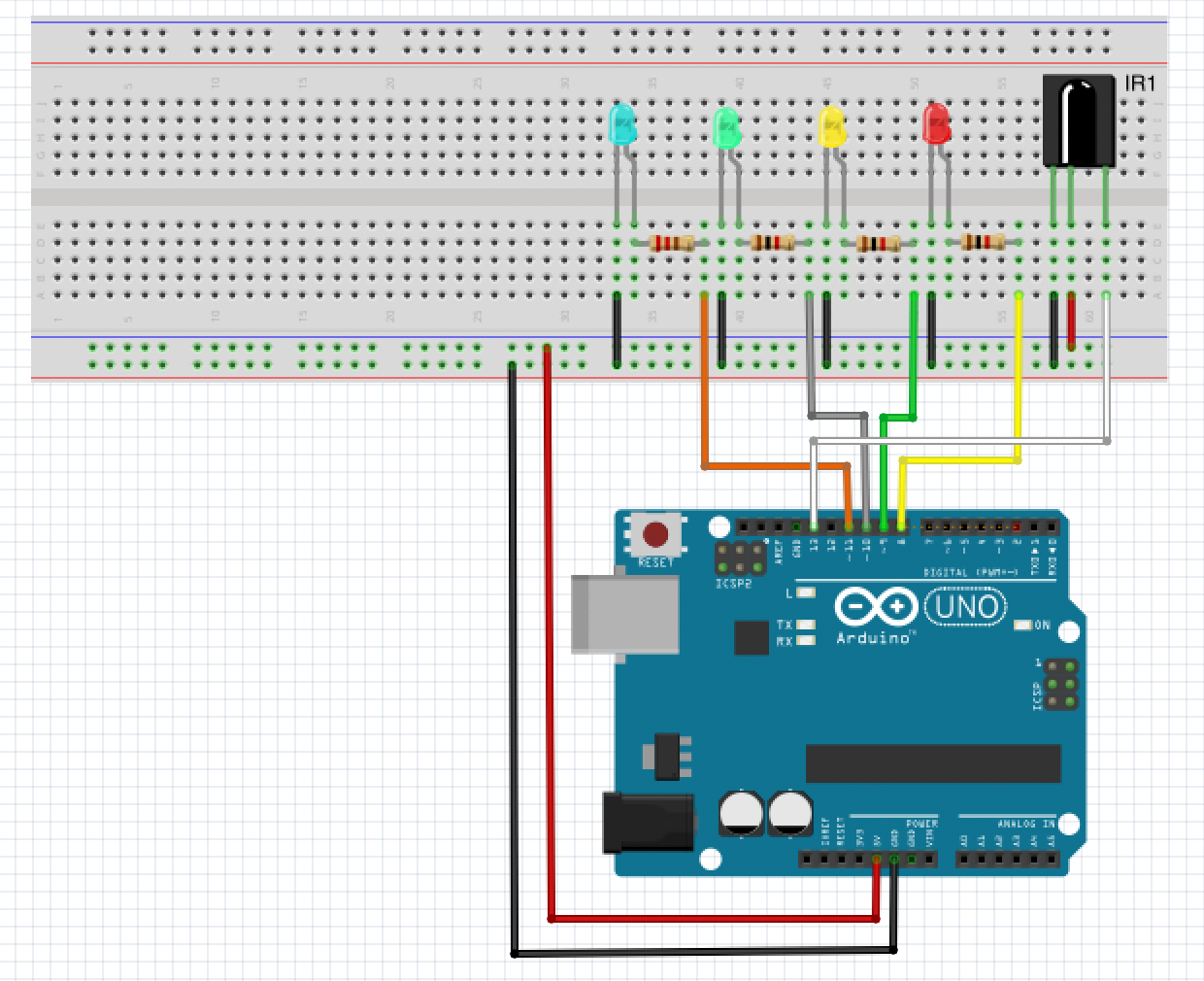
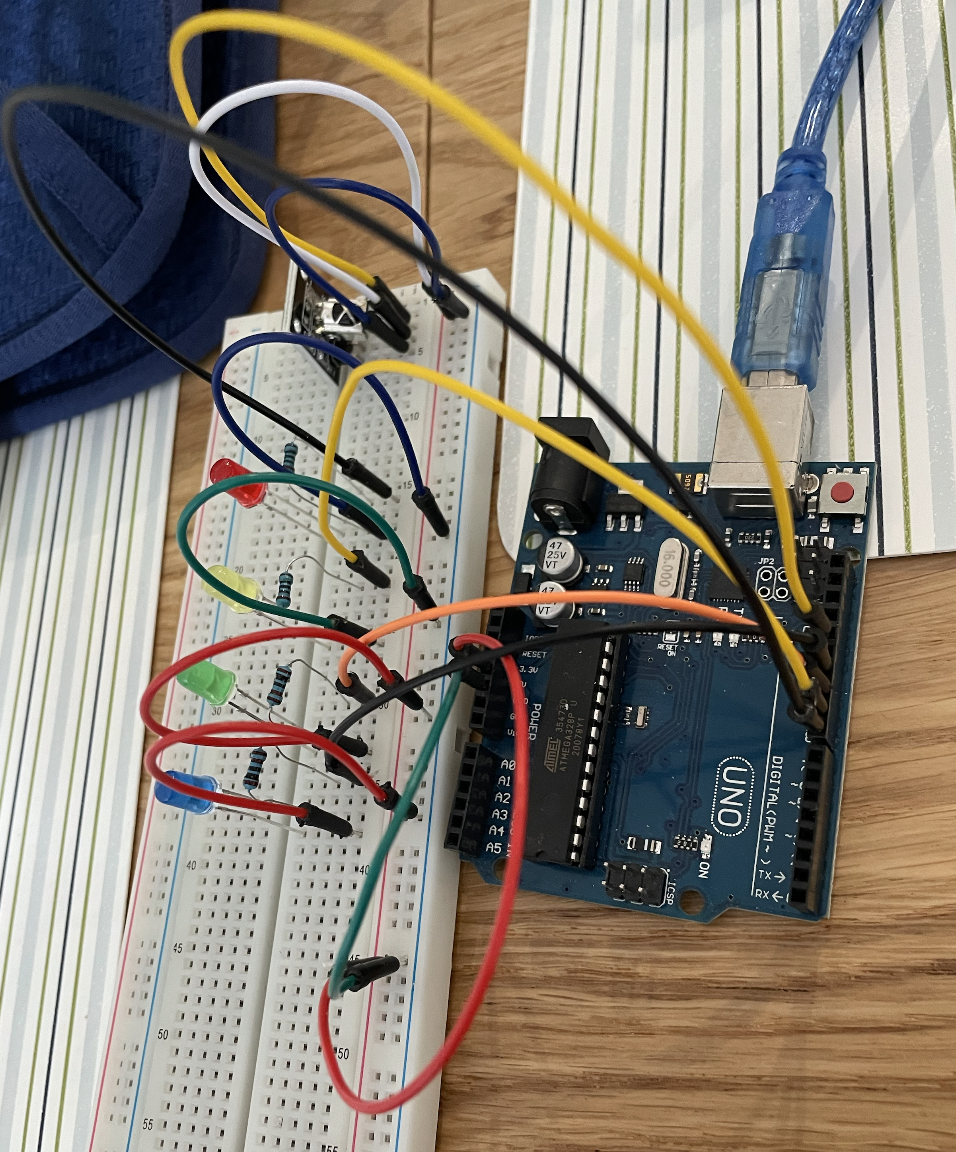
and as usually, assembled scheme:
The code, to make things work:
#include <Arduino.h>
#include <IRremote.h>
#include <IRremoteInt.h>

const int receiverPin = 13;
IRrecv irrecv(receiverPin, true);
decode_results results;
IRData* data;

const uint8_t redPin = 8;
const uint8_t yellowPin = 9;
const uint8_t greenPin = 10;
const uint8_t bluePin = 11;

void setup()
{
    Serial.begin(9600);
    // Configures the timer and the state machine for IR reception.
    irrecv.enableIRIn();
    Serial.println("Started");

    pinMode(redPin, OUTPUT);
    pinMode(yellowPin, OUTPUT);
    pinMode(greenPin, OUTPUT);
    pinMode(bluePin, OUTPUT);
}

void loop()
{
    // The main decode function, attempts
    // to decode the recently receive IR signal.
    if (irrecv.decode())
    {
        // If IR receiver data is available, returns pointer to
        // IrReceiver.decodedIRData, else NULL.
        data = irrecv.read();
        if (data != NULL) {
            translateIR();
            irrecv.resume();
        }

    }
}

void translateIR()
{
    Serial.println(getProtocolString(data->protocol));

    switch (data->command)
    {
        case 0x45:
            Serial.println("CH-");
            break;
        case 0x46:
            Serial.println("CH");
            break;
        case 0x47:
            Serial.println("CH+");
            break;

        case 0x44:
            Serial.println("Back");
            break;
        case 0x40:
            Serial.println("Forw");
            break;
        case 0x43:
            Serial.println("Play/Pause");
            break;

        case 0x7:
            Serial.println("-");
            break;
        case 0x15:
            Serial.println("+");
            break;
        case 0x9:
            Serial.println("EQ");
            break;

        case 0x16:
            Serial.println("0");
            break;
        case 0x19:
            Serial.println("100+");
            break;
        case 0xD:
            Serial.println("200+");

            digitalWrite(redPin, HIGH);
            delay(1000);
            digitalWrite(yellowPin, HIGH);
            delay(1000);
            digitalWrite(greenPin, HIGH);
            delay(1000);
            digitalWrite(bluePin, HIGH);
            delay(1000);
            break;

        case 0xC:
            Serial.println("1");
            blinkDionOnPin(redPin);
            break;
        case 0x18:
            Serial.println("2");
            blinkDionOnPin(greenPin);
            break;
        case 0x5E:
            Serial.println("3");
            blinkDionOnPin(yellowPin);
            break;
        case 0x8:
            Serial.println("4");
            blinkDionOnPin(bluePin);
            break;
        case 0x1C:
            Serial.println("5");
            break;
        case 0x5A:
            Serial.println("6");
            break;
        case 0x42:
            Serial.println("7");
            break;
        case 0x52:
            Serial.println("8");
            break;
        case 0x4A:
            Serial.println("9");
            break;

        default:
            // Serial.println("Unknown command");
            // irrecv.printIRResultMinimal(&Serial);
            // irrecv.printIRResultShort(&Serial);
            break;
    }
}

void blinkDionOnPin(int pin) {
    digitalWrite(pin, HIGH);
    delay(2000);
    digitalWrite(pin, LOW);
}
complete documentation on
IRRemoteu can find here
And small demo:
Share on: