Building a car with Arduino
arduino Arduino UNO Estimated reading time: 9 minutesHaving fun and learning something new - some of the best things that we can do.
Some time ago, I wrote about arduino and some basic stuff that we can do with various elements and components. Off cause, I didn’t cover every component that I played with, but some, that can be used today I did.
Another post that u can find interesting - how to observe serial ports on macOS
My son likes to play with a car (who didn’t? ;]). Play and learn - it’s a good way to go. So we decided to build a car - “with headlights” and “with auto-pilot” and “with remote control” and “with display” and “with light-sensors” and “with buzzer” and a few more :].
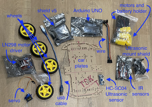
Components and tools
The list of needed components are next:
- L298N Motordriver x1
- Ultrasonic Sensor - HC-SR04 x1
- Arduino UNO x1 with USB cable x1
- Sensor shield V5 x1
- 4WD Smart Robot Car Chassis (baseplates) x1
- Wheels x4
- Engines x4
- Servo
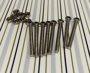
- Screws with nuts M3 x18
- Spacers M3x60 x6
- Resistor 220 Ohm x2
- LED lights x2
- Wires (a bunch :) - male-female, male-male, female-female
- Batteries AA x4
I bought parts from different sets, and without any instruction, so some of them are not perfectly fit ;].
Also I started within the simplest variant - without remote control and any additional sensors, all modifications will be added a bit later.
Tools:
- Solder iron
- Screwdriver
Soft:
- IDE Arduino/Visual Code
- Fritzing (optional, for schematic)
In total, a minimal set of components is:
Assembling
A lot of photos!
Before we actually starts, it’s good to see how all components are connected with each other, in other words, it’s good to see the schematic:
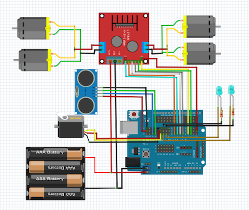
This scheme is the simplest one and does not include IR components and BLE modules; We can simplify it even more by removing LEDs
Let’s go step-by-step.
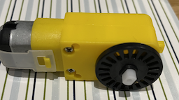
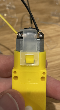
The actual assembling I started by soldering wires to the DC motors. This process takes a few sub-steps:
Prepare motor:
connect wires:
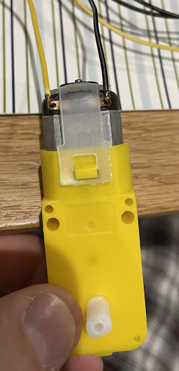
solder wires:
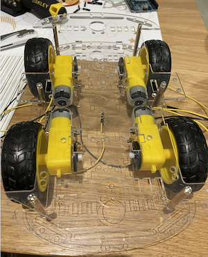
Now, we can start assembling the chassis and connect motors to them.
remove protection from acrylic chassis and holders:

prepare screws and nuts:
put motors on chassis and assemble them:


Next step - add wheels:
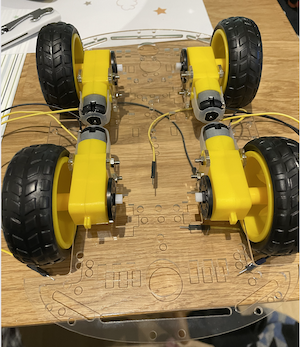
add spacers
and add top chassis
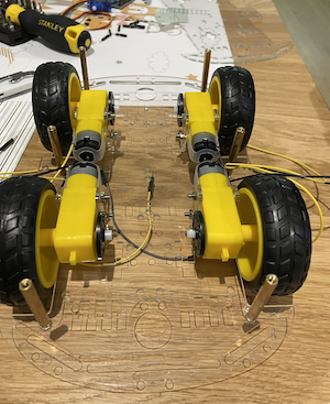
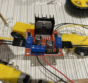
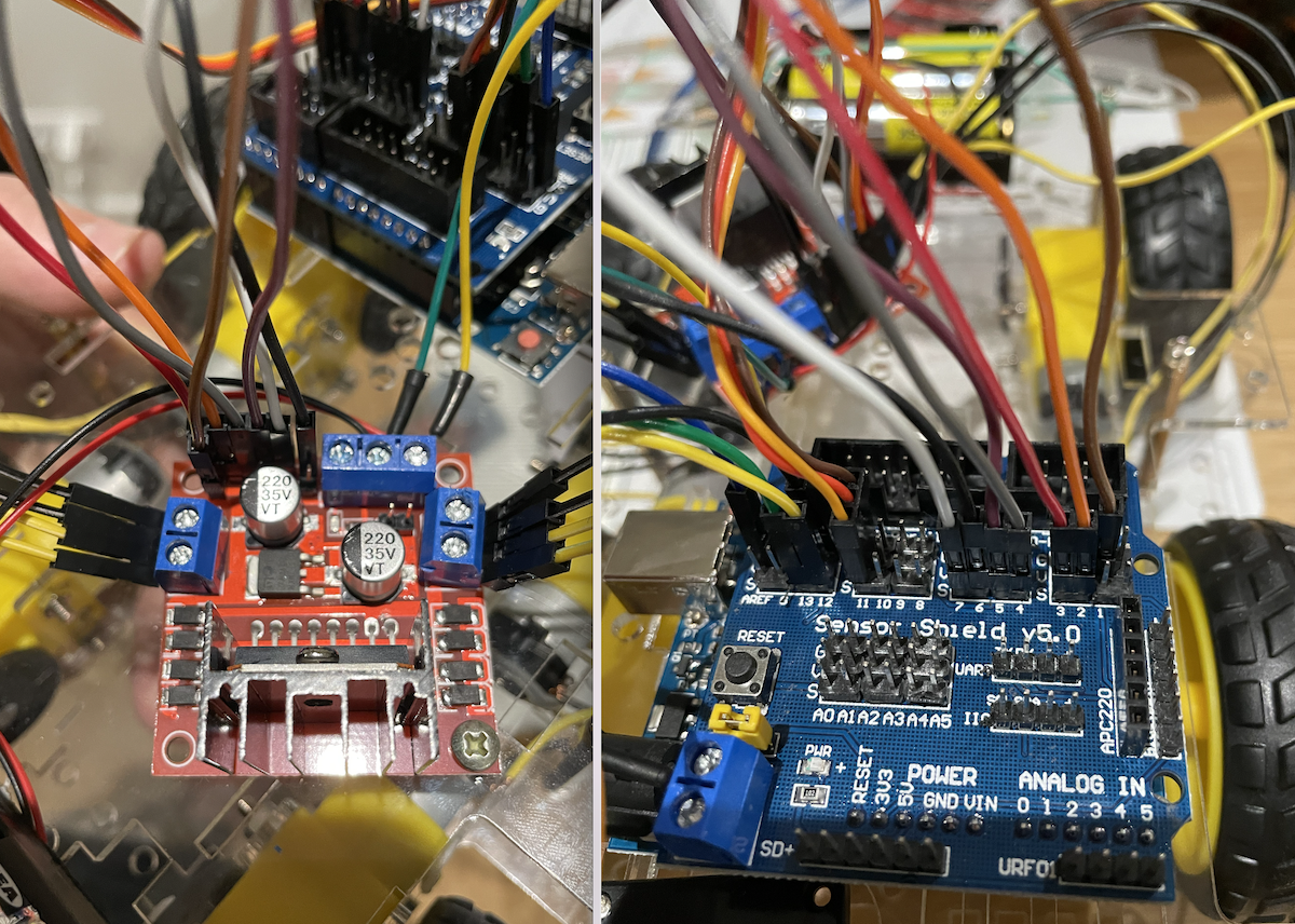
Now, it’s time to connect DC motors to L298N bridge:
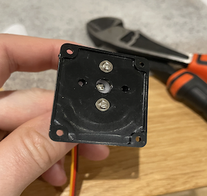
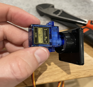
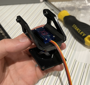
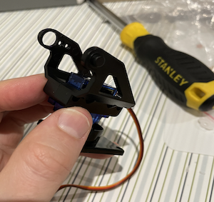
The next step is a bit messy - we should assemble servo. The components that I bought were a bit miss-aligned and can’t be assembled easily, so I manually adjust some plastic parts and then assemble the servo with its holder. After we should add an ultrasonic reader to the servo - I used wires to connect them.
The complete result shown on pics below:

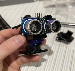

After this operations the car looks like this:

The next step is to combine the Arduino board with the sensor shield. I bought v5.
The schematic for this component is next:
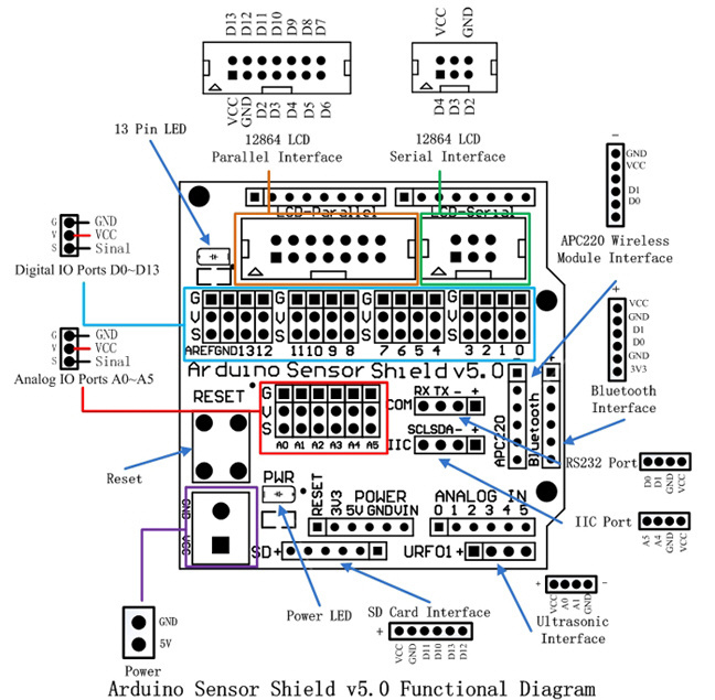
To use a shield, we should place it on the Arduino board and align it to the right side.
Make sure that all pins are in their places.
The final wiring looks like this:
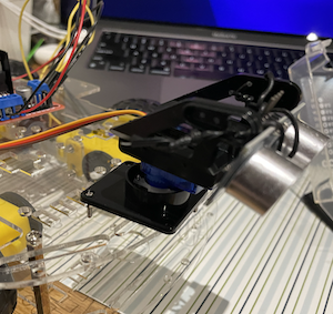
The full car photo:
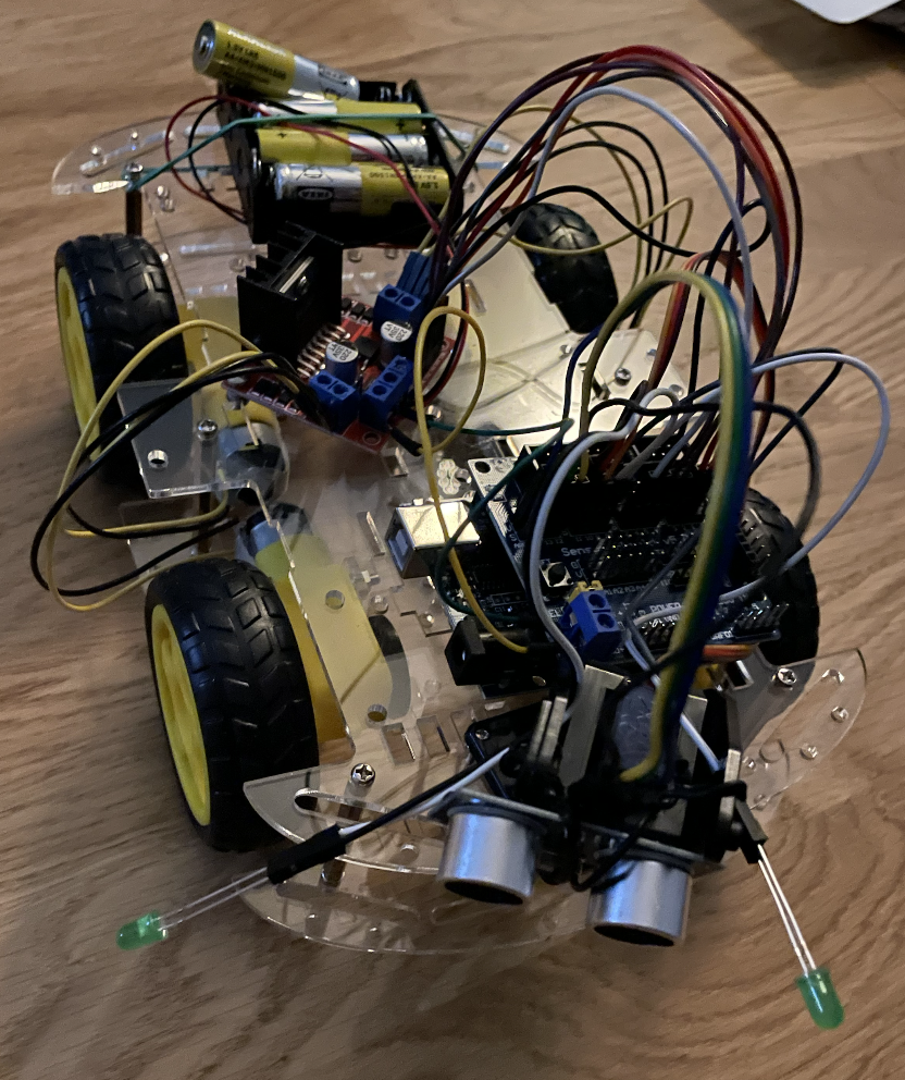
This is a minimal configuration that can be used for a car. Off cause we can use only 2 engines, we can reduce qty of wheels and makes some other modification, but this is another story.
Programming
To make our car movable, we need to add a few things.
- Need to control engines (DC motors and L298N)
- Use ultrasonic component to detect obstacles (servo and HC-SR04)
- Enable lighting (using LEDs) if obstacles occurs
I didn’t reinvent the wheel, so just grab the code from the Arduino forum and adjust a bit for my needs (unfortunately I lost the link, but u can easily google for it).
We can go step-by-step.
Define all pins
We have already assembled the car, some pins are used on an Arduino board to control specific components. It’s time to define them in the code.
Servo
For Servo we must define 3 pins and create an object instance
#include <Servo.h>

Servo servo;

const int ultrasonicPin = 13;
const int ultrasonicEchoPin = 12;
const int servoControlPin = 11;
It’s good to know, how servo works - according to doc, we can rotate it from 0 to 180 degrees. This mean, that we can scan for obstacle only “effective” zone - from 60 to 120 degrees. In other words:

so in code, this can be defined as next
#define PULSE_PROBE_COUNT 7
#define SERVO_START_POSITION 60
unsigned char scannedAngles[PULSE_PROBE_COUNT] = {
    SERVO_START_POSITION, 70, 80, 90, 100, 110, 120};
Motor
The whole motor pins and related values can be defined as next:
// L298N H bridge

enum MotorDirection
{
    LEFT,
    RIGHT
};

const int leftMotorPWMPin = 6;
const int in1Pin = 7;
const int in2Pin = 5;
const int in3Pin = 4;
const int in4Pin = 2;
const int rightMotorPWMPin = 3;
Other defines
We also need to define pins for LED and store distance info. This can be done like this:
unsigned int distances[PULSE_PROBE_COUNT];

// head light LEDs

const int leftDiodePin = 9;
const int rightDiodePin = 10;
Initialization
We are ready to configure initial state for all components:
void setup()
{
    configureUlstrasonic();
    configureBridge();
    configureServo();
    configureHeadLights();

    testMotors();
    initialScan();
}
In details:
void configureUlstrasonic()
{
    pinMode(ultrasonicPin, OUTPUT);
    pinMode(ultrasonicEchoPin, INPUT);
    digitalWrite(ultrasonicPin, LOW);
}

void configureBridge()
{
    pinMode(leftMotorPWMPin, OUTPUT);
    pinMode(in1Pin, OUTPUT);
    pinMode(in2Pin, OUTPUT);
    pinMode(in3Pin, OUTPUT);
    pinMode(in4Pin, OUTPUT);
    pinMode(rightMotorPWMPin, OUTPUT);
}

void configureHeadLights()
{
    pinMode(leftDiodePin, OUTPUT);
    pinMode(rightDiodePin, OUTPUT);
}

void configureServo()
{
    servo.attach(servoControlPin);
    servo.write(SERVO_START_POSITION);
}

void initialScan()
{
    delay(200);
    for (unsigned char i = 0; i < PULSE_PROBE_COUNT; i++)
        readNextDistance(),
            delay(200);

    servo.write(SERVO_START_POSITION);
}
readDistancewill be defined below
Loop
After everything is done and ready, we can define the main loop - scan surrounding space and move forward if space is free or backward and to some side if not.
To do so, we need to read data from an ultrasonic sensor in effective range, analyze it, and control or engines:
// MOVEMENT

// Set motor speed: 255 full ahead, −255 full reverse, 0 stop
void moveTo(enum MotorDirection m, int speed)
{
    digitalWrite(
        m == LEFT ? in1Pin : in3Pin,
        speed > 0 ? HIGH : LOW);
    digitalWrite(
        m == LEFT ? in2Pin : in4Pin,
        speed <= 0 ? HIGH : LOW);
    analogWrite(
        m == LEFT ? leftMotorPWMPin : rightMotorPWMPin,
        speed < 0 ? -speed : speed);
}

// SCAN

// Read distance from the ultrasonic sensor, return distance in mm
// Speed of sound in dry air, 20C is 343 m/s
// pulseIn returns time in microseconds (10ˆ−6)
// 2d=p*10ˆ−6s*343m/s=p*0.00343m=p*0.343mm/us
unsigned int readDistance()
{
    digitalWrite(ultrasonicPin, HIGH);
    delayMicroseconds(10);
    digitalWrite(ultrasonicPin, LOW);
    unsigned long period = pulseIn(ultrasonicEchoPin, HIGH);
    return period * 343 / 2000;
}

// Scan the area ahead by sweeping the ultrasonic sensor left and right
// and recording the distance observed. This takes a reading, then
// sends the servo to the next angle. Call repeatedly once every 50 ms or so.
void readNextDistance()
{
    static unsigned char angleIndex = 0;
    static signed char step = 1;
    distances[angleIndex] = readDistance();
    angleIndex += step;
    if (angleIndex == PULSE_PROBE_COUNT - 1)
        step = -1;
    else if (angleIndex == 0)
        step = 1;
    servo.write(scannedAngles[angleIndex]);
}
As I mention above, I didn’t reinvent the wheel and just grab this code from an unknown author on the Arduino forum.
That’s it. We are ready to go.
The full code here
#include <Servo.h>

Servo servo;

// Servo

const int ultrasonicPin = 13;
const int ultrasonicEchoPin = 12;
const int servoControlPin = 11;

// L298N H bridge

enum MotorDirection
{
    LEFT,
    RIGHT
};

const int leftMotorPWMPin = 6;
const int in1Pin = 7;
const int in2Pin = 5;
const int in3Pin = 4;
const int in4Pin = 2;
const int rightMotorPWMPin = 3;

// Ultrasonic

#define PULSE_PROBE_COUNT 7
#define SERVO_START_POSITION 60
unsigned char scannedAngles[PULSE_PROBE_COUNT] = {
    SERVO_START_POSITION, 70, 80, 90, 100, 110, 120};
unsigned int distances[PULSE_PROBE_COUNT];

// head light LEDs

const int leftDiodePin = 9;
const int rightDiodePin = 10;

void setup()
{
    configureUlstrasonic();
    configureBridge();
    configureServo();
    configureHeadLights();

    testMotors();
    initialScan();
}

void loop()
{
    readNextDistance();
    analyzeDataAndProceed();

    delay(50);
}

void analyzeDataAndProceed()
{
    unsigned char tooClose = 0;
    for (unsigned char i = 0; i < PULSE_PROBE_COUNT; i++)
        if (distances[i] < 300)
            tooClose = 1;
    if (tooClose)
    {
        moveTo(LEFT, -180);
        moveTo(RIGHT, -80);
        digitalWrite(leftDiodePin, HIGH);
        digitalWrite(rightDiodePin, HIGH);
    }
    else
    {
        moveTo(LEFT, 255);
        moveTo(RIGHT, 255);
        digitalWrite(leftDiodePin, LOW);
        digitalWrite(rightDiodePin, LOW);
    }
}

// CONFIG

void configureUlstrasonic()
{
    pinMode(ultrasonicPin, OUTPUT);
    pinMode(ultrasonicEchoPin, INPUT);
    digitalWrite(ultrasonicPin, LOW);
}

void configureBridge()
{
    pinMode(leftMotorPWMPin, OUTPUT);
    pinMode(in1Pin, OUTPUT);
    pinMode(in2Pin, OUTPUT);
    pinMode(in3Pin, OUTPUT);
    pinMode(in4Pin, OUTPUT);
    pinMode(rightMotorPWMPin, OUTPUT);
}

void configureHeadLights()
{
    pinMode(leftDiodePin, OUTPUT);
    pinMode(rightDiodePin, OUTPUT);
}

void configureServo()
{
    servo.attach(servoControlPin);
    servo.write(SERVO_START_POSITION);
}

void initialScan()
{
    delay(200);
    for (unsigned char i = 0; i < PULSE_PROBE_COUNT; i++)
        readNextDistance(),
            delay(200);

    servo.write(SERVO_START_POSITION);
}

// CONTROL

// Set motor speed: 255 full ahead, −255 full reverse, 0 stop
void moveTo(enum MotorDirection m, int speed)
{
    digitalWrite(
        m == LEFT ? in1Pin : in3Pin,
        speed > 0 ? HIGH : LOW);
    digitalWrite(
        m == LEFT ? in2Pin : in4Pin,
        speed <= 0 ? HIGH : LOW);
    analogWrite(
        m == LEFT ? leftMotorPWMPin : rightMotorPWMPin,
        speed < 0 ? -speed : speed);
}

void testMotors()
{
    static int speed[8] = {
        128, 255, 128, 0,
        -128, -255, -128, 0};
    moveTo(RIGHT, 0);
    for (unsigned char i = 0; i < 8; i++)
        moveTo(LEFT, speed[i]), delay(200);

    for (unsigned char i = 0; i < 8; i++)
        moveTo(RIGHT, speed[i]), delay(200);
}

// Read distance from the ultrasonic sensor, return distance in mm
// Speed of sound in dry air, 20C is 343 m/s
// pulseIn returns time in microseconds (10ˆ−6)
// 2d=p*10ˆ−6s*343m/s=p*0.00343m=p*0.343mm/us
unsigned int readDistance()
{
    digitalWrite(ultrasonicPin, HIGH);
    delayMicroseconds(10);
    digitalWrite(ultrasonicPin, LOW);
    unsigned long period = pulseIn(ultrasonicEchoPin, HIGH);
    return period * 343 / 2000;
}

// Scan the area ahead by sweeping the ultrasonic sensor left and right
// and recording the distance observed. This takes a reading, then
// sends the servo to the next angle. Call repeatedly once every 50 ms or so.
void readNextDistance()
{
    static unsigned char angleIndex = 0;
    static signed char step = 1;
    distances[angleIndex] = readDistance();
    angleIndex += step;
    if (angleIndex == PULSE_PROBE_COUNT - 1)
        step = -1;
    else if (angleIndex == 0)
        step = 1;
    servo.write(scannedAngles[angleIndex]);
}
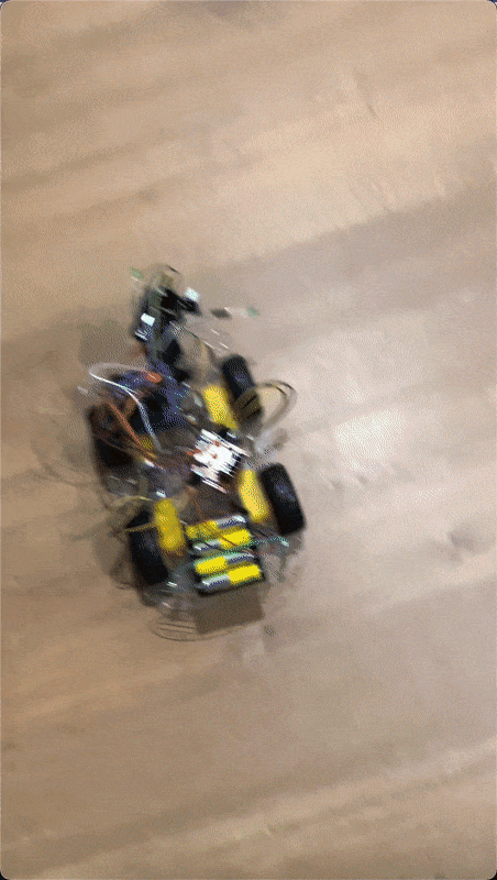
Demo
Resources
Share on: